CNC Machined Halo weapons. Pure UNSC Bada$$ery. Airsoft builds :D

Status
Not open for further replies.
I have been trying to figure out myself what rifle would be good to convert since I can't build one from scratch(but I can 3d model a body). What i have found is the British armed forces rifle don't know the name off the top of my head has the same kind of design and I believe they have a version that shoots the 7.62 round(could be mistaken though). Or else for me I was planning on using a m4 version 2 gearbox but just mounting it in the back to make it a dmr since the halo dmr has that huge stock that I could also mount the motor and possibly a battery too.

It's probably best just to follow in Deadz foot steps. If you were to make a shell, the gun still would require heavy modification.
 
That sounds good. You might need to figure out something for the trigger since it's gonna be a bit away from the gearbox.

Oh ya I was not even going to get the fun I would just buy the internals and build 3d mounts for them in the shell.

Bout time I join in lol.
So my plan was to, using V2 internals, kick the gearbox as far back in the body as possible for my AR and BR builds. I was going to then make a custom magazine and bb feed path since not everything is m4 compatible. The hop and barrel would sit in their normal place. I'm gunna put the battery in the fore grips. And as far as the trigger goes, I was going to do it like any other bullpup where there's a hinge linkage that just goes back to manipulate the trigger switch on the gearbox. All of the space was going to be carved out of the bodies similar to how I did it for this build. Only a lot easier since they're aeg's and not gbbrs. lol

I have seen people just put a shell around guns and they never look right. A while ago I tried carving out the center of a cast and got pretty close. I'm going to pick that build thread up after this one and just call my first attempt the alpha haha. I will probably end up having to 3D print my bodies as finding machine shops for this is hard enough. And since I have no funding for this project, I need to find alternatives.

lol thanks for jumping in. I'm no engineer so I'm completely lost on this stuff lol. Also, based on your designs, have you been able to conclude with any specs? FPS, RPM, Effect Range, etc..
 
lol thanks for jumping in. I'm no engineer so I'm completely lost on this stuff lol. Also, based on your designs, have you been able to conclude with any specs? FPS, RPM, Effect Range, etc..

No idea. lol. That all really will be found out when everything is together. I intend on installing an npas so that I can adjust the fps depending on where I play. I want to have it around 500 fps. Rpm is non-existant as it's going to be semi only.
Range, I have no idea. lol. As far as I can make it really. I want to put a 640mm tighbore in it so that should help a lot. It's really just boing to boil down to making sure I can get sufficient gas outflow in both directions. Out the barrel and to cycle the bolt. It'll all be determined when built.
 
Bout time I join in lol.
So my plan was to, using V2 internals, kick the gearbox as far back in the body as possible for my AR and BR builds. I was going to then make a custom magazine and bb feed path since not everything is m4 compatible. The hop and barrel would sit in their normal place. I'm gunna put the battery in the fore grips. And as far as the trigger goes, I was going to do it like any other bullpup where there's a hinge linkage that just goes back to manipulate the trigger switch on the gearbox. All of the space was going to be carved out of the bodies similar to how I did it for this build. Only a lot easier since they're aeg's and not gbbrs. lol

I have seen people just put a shell around guns and they never look right. A while ago I tried carving out the center of a cast and got pretty close. I'm going to pick that build thread up after this one and just call my first attempt the alpha haha. I will probably end up having to 3D print my bodies as finding machine shops for this is hard enough. And since I have no funding for this project, I need to find alternatives.

HaHa love that you are still trying to do this. I know a little about cadding that I taught myself so i'm no engineer but cant wait to see this. I also imagine that this would be a so much harder to do a gas blow back(i'm not even going to try) so i wish you luck.
 
Geez, this build is insane, and I one that I bet all of us that play airsoft have been dreaming of for years :p

What's your expected budget on this bad boy, it can't be cheap by any stretch of the imagination.
 
Geez, this build is insane, and I one that I bet all of us that play airsoft have been dreaming of for years :p

What's your expected budget on this bad boy, it can't be cheap by any stretch of the imagination.

Expected budget is $0 lol. Um. It's kinda complicated really. So the school is unable to fund this project. I have asked a couple times and there is no ability to receive any funding. Anything that needs to be purchased will end up coming out of my pocket unfortunately. The parts are out to a number of different machine shops who are looking at them right now. If any of these parts can not be made for free, then I will most likely end up having to set up some sort of crowd funding or try to find some sponsors. So yeah. We'll see in the coming weeks where things go. As of now I'm about $300 in the hole with the components that I've purchased. I'm expecting to have to shell out more in order to purchase some of the parts.
 
Quick update. So I've gotten some responses from a couple of my contacts. I've got three shops that will allow me to work on making parts as well as assist with the machining of a handful of parts for the rifle. Granted that these are mostly the internal and more simple components. A number of parts I am pricing out to have 3D printed. Still waiting on hearing back on the other machine shops to make the more complicated parts. I will also be getting material quotes next week and purchasing material. I will also be speaking with some other people whom I have worked with in the past to try to sponsor some of this project to offset some of the cost. I should also be able to get into our CNC lab with in the next week or so so I can start machining some of the parts with the HAAS CNC's.
 
So where exactly are you getting the dimensions from?

So I took the .obj file for the Halo 3 SR and opened it into a 3D modeling software. I then converted it into a .dxf format so that I could open it up in Solidworks. After the half hour or so it took to convert the file (had to leave my laptop alone. Didn't want to mess with it during the conversion haha.) I saved it as a Solidworks assembly to open up later. That file is where I got my measurements from. However, it did not come in properly scaled. I looked up the rifle in the Halo wiki and found that it's 187.5 cm or 73.82 inches. I then created a conversion factor for myself so that when I entered the dimension from the .dxf file it spit out the to-scale length that I needed. Lets just say that I filled up a couple pages in my notebook figuring out the external dimensions of stuff. My model is roughly 3mm off of what the Wiki length is so I'd say I'm pretty darn close to full scale. Haha.

As far as the internal dimensions goes, I just physically measured the internal components of a WE M4 Gbbr. Since I don't own one I borrowed a buddy's. But over winter I bought an internal kit so I based some of it off of that as well. The rest of the design work is getting stuff to line up right and cut as much weight as possible while keeping the strength and integrity of the pieces.
 
You are gonna do FEA ?!......... You are My Hero!

This one's for you peterthethinker ;)

So I've started on the FEA road. Imported the Bolt Carrier (which is the only part that we will be doing finite element analysis on at the moment) into HyperWorks/HyperMesh.
HM BCG 1.png

And then did a 2D automesh with element size of .05 inches

HM BCG 2.png

HM BCG 2.5.png

After that, I made a new component and created the 3D Tetramesh. For those who are unfamiliar with FEA, in order to do a full analysis on a 3D part, a 3D tetramesh or hexamesh is needed.

HM BCG 3.png

The conversion wasn't too bad. It only took a minute or two.
And here's the tetramesh:
HM BCG 4.png

HM BCG 5.png

HM BCG 6.png

This weekend, we will work on doing the static analysis (for just the BCG when under normal spring force) and eventually the dynamic analysis (for impact loading).


Ok. So now for non-FEA related updates...
Got ahold of another machine shop and sent him parts. Hopefully he will be able to turn the barrel components. Other than that, I was able to find out that our MMAE (Mechanical, Materials, and Aerospace Engineering) department, which is my department lol, is trying to encourage students to 3D print parts. And the best part is that the printers are free! The 3D printers also have a tolerance of .1 mm which is awesome! This means that I will be able to print a number of parts in house in high quality. So I will be making full use of those over the coming weeks. I'm planning on printing the piston guides (top and side), the Muzzle break, and possibly some of the other internal pieces that I intended on making plastic anyways. I also intend on printing the mounting components for the camera in the scope assembly.
cam.png

I also started modeling the Scope assembly with the rough size estimates of the display.
lcd disp.png
Display.png

So it doesn't fill the entire area but neither does it in the game files. It is a 4:3 so it should be plenty fine. I might add some side panels inside to block any incoming light from the scope so that the only thing visible internally is the display. The display is sunken a little into the scope as in the game. This also helps provide extra room above and below since it is just about the same height as the sunshade section. The display has finally shipped so it should be in my hands within a weeks or so.

I may also end up printing the scope housing, but I will have to see on that if I can get it machined first or not.

Next Friday I will be working in a machine shop to make the skids and the hammer pieces from steel so I will soon be posting pics of finished physical pieces! We're getting there guys! :D
 
Wooh! Big step in the project today! The manufacturing process has officially started. Yay! We'll get to that in a minute. But for now, other updates.

So I've made a list of all of the parts with quantity, material, completion stages etc.

parts.png

Also, I've gotten some responses from the companies that I have contacted. Some good and some bad... A couple of the companies do not have the proper tooling for the level of detailed manufacturing on some of these parts. A number of the contacts have opened their shops and offered to assist with making parts.

support.png

As I said, next Friday I will be making the steel parts. I've completed the safety training session for my campus so I now have access to the CNC's and mills which means that I will be able to start really machining some of these parts in the coming weeks.

I have printed a couple of parts today. The piston guides have been printed (the white parts).

WE pic.png

WP_20160226_10_50_58_Pro.jpg

The Muzzle break has been started but is a 16 hour + print so that I won't have updates for a couple of days since the shop is closed on the weekend.

WP_20160226_10_47_16_Pro.jpg


The printed parts turned out pretty good. I need to take some sand paper to them though but not bad overall.
Top piston guide:
WP_20160226_15_29_42_Pro.jpg

WP_20160226_15_37_44_Pro.jpg

Side piston guide:
WP_20160226_15_29_35_Pro.jpg

WP_20160226_15_38_21_Pro.jpg

Proof of concept:
WP_20160226_17_01_22_Pro.jpg

And I've also printed the post for the muzzle break. I wanted to make this a separate part so that i could paint it since depending on the picture that you look at, it is potentially a different color than the rest of the muzzle break.
WP_20160226_15_29_25_Pro.jpg

WP_20160226_17_03_24_Pro.jpg

On Monday, I will also be printing out parts of the scope assembly. I will be printing the camera mount, camera mount rail, scope tubes (bottom and top) and the optic clamp to keep the 7x scope in place. I'll add the little ridges to the scope this weekend so that it will be ready for Monday to print.
scope tube assem.png

That's it for now. Stay tuned for Tuesday. I'll have more parts!
 
Alrighty. I've got some more parts for you guys! First off, I've got some parts on the print bed right now. I've decided to print the scope assembly as much as possible in order to get the more complex details of the scope rather than machine it. And since it's free, why not?! Haha.

I've updated the scope tube with a couple of features. I added the angle faces to give the scope some more detail. I do intend to coat the entire scope (when finished) in that spray rubber stuff to provide the proper texture and an additional protective layer to prevent damage from bbs.

scope update.png

Since this is being printed. I've also converted the tapped hole callouts into screw taps so that the threads will be built into the part during printing. The holes on the bottom are for #4 screws, so I have no idea how they will turn out. We will see tomorrow when I pick the pieces. Up.

scope threads.png

On the top there are 1/4 inch threads that have been cut using the same method and will be printed tomorrow.

Today I printed the bottom scope tube, the 7x scope keeper, I'm printing essentially the parts that hold the optics in place which is this assembly:

scope print.png

the camera rail and the camera mount. Here's some in-progress print pics.

WP_20160301_09_22_33_Pro.jpg

WP_20160301_09_38_13_Pro.jpg

Ok. Now on to the finished parts for today. So the muzzle break was printed over last night. And... um. Yeah. So, you know how people say that it's really hard to understand the true scale of something when you build it in CAD? Well, yeah. They might be right...

WP_20160301_09_42_51_Pro.jpg

Had to clean out the support material (the rough pieces).

WP_20160301_09_42_57_Pro.jpg

Here it is cleaned up a little.
WP_20160301_10_19_19_Pro.jpg

And I put the post on it to see what it would look like. That's on my ipad (for scale). This thing is going to be massive. And I can't wait.

WP_20160301_12_13_50_Pro.jpg

Oh yeah. Last thing. So I started adding some color to the pieces. I still need to refine the color scheme but I just made a rough version and it is gorgeous.

color.png
 
Okay. Got some more updates! Over this week, we've had some ups and some downs. But we'll start with the good news right now.

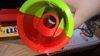
The scope tube components have been printed and will need to be polished up. But now I can work on fitting the scope components into the printed parts. So with the scope, I have the two halves of the tube printed, the 7x retainer, and the mount for the camera all printed.

WP_20160302_09_15_37_Pro.jpg

WP_20160302_09_29_52_Pro.jpg

WP_20160303_10_47_59_Pro__highres.jpg

I also re-printed the camera mount since the first time it came out really rough.
WP_20160303_10_34_33_Pro__highres.jpg

WP_20160303_10_47_30_Pro__highres.jpg

And I started putting some of the components in place in the tube.
WP_20160303_10_52_25_Pro__highres.jpg


WP_20160303_10_59_02_Pro__highres.jpg

WP_20160303_10_58_05_Pro__highres.jpg
I also started working on making the steel components at a machine shop on Friday.

I started by cutting out the pieces for the hammer pieces.
WP_20160304_10_35_53_Pro__highres.jpg

And then marked the centers for the dowel pin holes to be drilled.
WP_20160304_10_46_27_Pro__highres.jpg

The holes were then drilled and reamed for a 1/8'th inch rod to fit in.
WP_20160304_12_22_50_Pro__highres.jpg

WP_20160304_13_04_50_Pro__highres.jpg

And the skids were also started. 2inch wide by 1/5 inch high steel plate was cut in 1.5 inch wide pieces to form the base shapes of the skids for the bipods.
WP_20160304_10_51_51_Pro.jpg

A hole was then drilled through for a 5/16th screw and a counter bore was then added so the bolt would be recessed.
WP_20160304_10_55_54_Pro__highres.jpg

WP_20160304_11_36_17_Pro__highres.jpg

WP_20160304_12_23_15_Pro__highres.jpg

WP_20160304_10_09_12_Pro__highres.jpg

These steel blocks will then be taken to a mill so I can machine out the slot in the center. The hammer parts are being micro-welded right now.

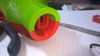
Ok. so that's where I'm at with parts. I still need to finish the surfaces of the muzzle break and the scope tube.

Now for the bad. On Thursday morning I spoke with our CNC shop manager about making a couple of parts in the shop, specifically the magazine shells. He said that our machines could make the two pieces, so I went out and purchased a $150 chunk of aluminum for the mag shells. About a half hour after I made the order, I received an email from my professor forwarding me an email from the shop manager to my professor and CC'ing the Dean of engineering asking if the project would be acceptable. Apparently the shop manager did a quick google search and saw one website that said airsoft was illegal in Chicago, which is incorrect. My professor asked if we could revise the project and I agreed (which I'll explain what we will be doing in a bit). After speaking with my friend who is a Chicago police officer confirming that you can own airsoft guns in Chicago, but just not bring them out in public, as well as looking up the specific Chicago ordinance stating that airsoft components can be manufactured in Chicago so long as the parts will be transported intrastate, interstate, or overseas (which is the intent), I spoke with my professor again. He agreed with me that there was a misunderstanding of the project and of Chicago laws. He also reached out to the shop manager some (my professor is totally for this project and thinks this issue is really stupid which now makes him the coolest college professor at IIT :D ). So as of right now, we have agreed to not manufacture the part that holds the hop up unit this semester (which is something that I can do on my own to finish this project yay!). We are trying to tip-toe around the bs bureaucracy of the current situation. As of now we will be able to move forward with the project again. This all made for an interesting 24 hours so we'll see where this goes from here.

This week I am also working on setting up a meeting with some engineers to discuss the manufacturability of components to make things easier to machine. My spring break is also coming soon so I will be able to make some more parts in the coming weeks.
 

Attachments

  • WP_20160303_10_59_02_Pro.jpg
    WP_20160303_10_59_02_Pro.jpg
    585.6 KB · Views: 212
  • WP_20160303_10_58_05_Pro__highres.jpg
    WP_20160303_10_58_05_Pro__highres.jpg
    1.8 MB · Views: 196
  • WP_20160303_10_59_02_Pro__highres.jpg
    WP_20160303_10_59_02_Pro__highres.jpg
    1.8 MB · Views: 220
Couple of miscellaneous updates. So the past couple of days have been a rollercoaster of craziness. After speaking with my professor quite a bit, we came up with a new proposal as I described above and submitted it to the Dean. The Dean unfortunately has refused to respond to our email essentially creating a pocket veto of the proposal. So she's now just playing politics. I spoke with my professor some more in person today and we agreed that the only thing that we can do is digitally analyze the assembly and do a sort of "drop test."

This essentially would have meant that the project would be dead in the water and never make it past the digital phase which is a no go. I was able to get some more clarifications from my professor later today and we are basically to the point where if I decide to take the designs and see the project materialize by making the parts from outside manufacturers (aka not on campus) then I am technically not doing anything wrong. So on that note, progress will resume as normal but now with more computer analysis of the assembly. So yay I guess.

On another note, I was finally able to figure out the grip for the battle rifle. I ended up cutting out a chunk of the body and simplified a bunch of the cuts.
battle rifle body.png

battle rifle body grip.png

And here's the grip that I made. I made a series of splines so that I could loft their faces to make a nice flow.
BR grip front.png

BR grip.png

This part would obviously be 3D printed haha. And here is the revised assembly with the new cleaner components.
battle rifle.png

Here's the comparison between what it was and where we're at now:
BR compare.png

I'll see if I can get these eventually printed or maybe even the entire gun. But we will start with one thing at a time haha.

Welp, we're making progress guys. Slowly but surely. But for now, you'll just have to settle for screenshots. ;)
side by side.png
 
I'm baaaack! :D

Ok. So I am now finally into production mode. Over the next four months, I will be attempting to build/assemble/complete this project. Target date of completion is May, 20th (hopefully sooner though). In addition, I will also be attempting to complete the Battle Rifle as an AEG (automatic electric gun). The weekend of May, 20th and 21st is a big 2-day airsoft event at which I intend on debuting these projects. This means one thing, more content, and hopefully, more consistent updates! Over the next couple of days, I will try to get you guys caught up with everything, as a lot has happened.

Let's start with the big news first:

I am now in the final stages of refining the design. I have worked with some fellow engineers/machinists to go over the designs and to make sure that they are machinable. Over this week, I will be making my final revisions and then send out the parts to get quoted this weekend. Given the company's timetable, I should hear back at the end of this month. Once I get the quote, the order will be placed, and then it's just 4-6 weeks until I will have parts in hand (Yay!). A handful of smaller components will be machined by myself during that time.

Next:
I have purchased a couple of 3D printers. One small one that I've had since September, and a larger one arriving in March. Using the small printer, I have been progressively printing a couple of the components, like the Chamber and the Gas Tube.

WP_20170120_20_05_15_Pro_zpspvoy0hzu.jpg

WP_20170115_22_42_34_Pro_zpsp1ppesfj.jpg

WP_20170112_17_31_38_Pro_zpsrhxm60ub.jpg


Once I finish printing the Chamber, I will begin to prep these pieces to make molds so I can cast whole versions of these out of urethane resin since 3D printed pieces are fairly brittle and a little wonky haha. There are a couple of other internal components that I will 3D print as well but I will not make casts of those and they should be sufficient on their own.


I also ordered the aluminum tubes for the outer barrel. Here's a photo to compare the scale of the SR to a Barrett .50cal airsoft rifle. I wasn't able to fit the tube in the muzzle break at the time of this photo, nor is the Chamber on it, so the barrel looks a little long in this photo. Either way though, it's still huge.

WP_20170112_17_31_20_Pro_zpsjamlexfd.jpg


I will also begin to prep the break to make a mold and cast of over the coming weeks as well as the scope which is together for fitting before I clean it up.

WP_20170122_20_28_52_Pro_zpsjkqf4gzu.jpg


I will go over my stuff and see what I want to put in here. I have a couple of reports that I've done on this while I am finishing my Masters that I will probably add for completeness. But for now, I will leave you guys with some eye candy and hopefully some good news at the end of the week! Thanks for bearing with me. This project has not been easy (and as the next couple of months roll in, it sure won't be cheap haha.)


full%20render_zpsicweelql.jpg


internal%20render_zps2r9ssgwx.jpg
 
Great work! Hey, have you heard of the DAS M4A1? It's and AEG that operates like a GBBR. When this new tech advances further, I'm defiantly gonna make me a DMR ;]
 
Status
Not open for further replies.
Back
Top